Beam Section Holder TPH F 80

Application
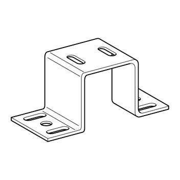
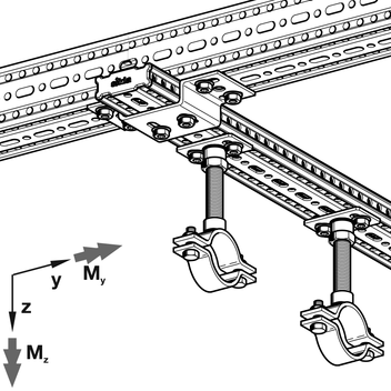
Interface element to connect 90° intersecting Beam Sections F80. Alternatively the Beam Section Holder TPH may be used to connect only one beam section to an even surface with suitable wall anchors or with cast-in channel accessories.
Installation
Connecting one Beam Section TP F 80 90° to another one by using 6 x Self Forming Screw FLS F applied through all elongated holes. Connecting to any other surface or member by using 2 x Self Forming Screws FLS F through the two elongated Slots on the top of the Beam Section Holder TPH F 80 plus 2 appropriate fixing elements up to 1/2" (M12) through the two holes “d1”.
Technical Data
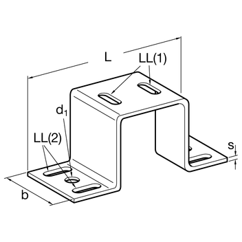
| Type | Dimensions L x b x s [in] | ø d1 [in] | Elongated slot LL(1) d x a [in] | Elongated slot LL(2) d x a [in] | Perm. load unter 90° to beam axis Fy = Fz [kip] |
|---|---|---|---|---|---|
| TPH F 80 | 7 1/8" x 1 15/16" x 1/6" | 1/2" | 7/16" x 13/16" | - | 1.57 |
| TPH F 80 C | 7 13/16" x 3 1/8" x 1/6" | 9/16" | 7/16" x 13/16" | 7/16" x 13/16" | 2.25 |
| Type | Dimensions L x b x s [mm] | ø d1 [mm] | Elongated slot LL(1) d x a [mm] | Elongated slot LL(2) d x a [mm] |
|---|---|---|---|---|
| TPH F 80/30 | 181 x 50 x 4 | 13 | 11 x 20 | - |
| TPH F 80/30 C | 199 x 80 x 4 | 14 | 11 x 20 | 11 x 20 |
| TPH F 80 | 181 x 50 x 4 | 13 | 11 x 20 | - |
| TPH F 80 C | 199 x 80 x 4 | 14 | 11 x 20 | 11 x 20 |
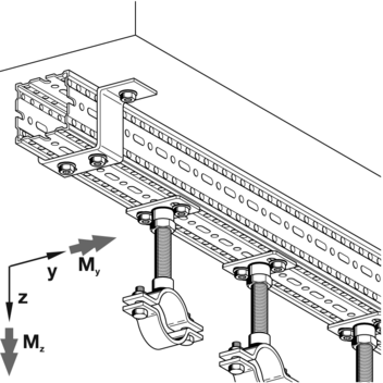
| Type | Fx [kN] | Fy [kN] | Fz [kN] | My [kNm] | Mz [kNm] |
|---|---|---|---|---|---|
| TPH F 80/30 | 6.2 | 20.8 | 13.6 | 0.9 | 0.9 |
| TPH F 80/30 C | 6.2 | 12.7 | 12.3 | 0.6 | 0.5 |
| TPH F 80 | 6.2 | 20.8 | 13.6 | 0.9 | 0.9 |
| TPH F 80 C | 6.2 | 12.7 | 12.3 | 0.6 | 0.5 |
The above load data indicates permissible loads and includes Partial Safety Factors γM2 = 1.25 (EN 1993-1-8:2010-12,
Tab. 2.1) and γG = 1.35 (EN 1990:2010-12, Tab. A1.2(B)) for general permanent actions.
| Material: | Steel, HCP |
Also available with DUALSHIELD for high corrosion protection within C5H environments.
Approvals / Conformity
![]()